Centrifugal Blowers
Technical Data
Single Stage SISW / DIDW · 0.25 HP to 100 HP
Complete performance specifications, discharge configurations and drive options for Shivam Engineering And Fabricators & AIR KING Centrifugal Blowers.
Centrifugal Single Stage
SISW / DIDW Blower
Range: 0.25 HP to 100 HP · Volume: 100 CFM to 60,000 CFM · Pressure: 25 mm St.WC to 3000 mm St.WC
| Motor HP | 1" | 2" | 3" | 4" | 6" | 8" | 10" | 12" | 16" | 20" | 24" | 28" | 32" | 36" | 44" | 50" |
|---|---|---|---|---|---|---|---|---|---|---|---|---|---|---|---|---|
| 0.25 HP | 750 | 400 | — | — | — | — | — | — | — | — | — | — | — | — | — | — |
| 0.50 HP | 1500 | 800 | 500 | 400 | 320 | 260 | 200 | 160 | 130 | — | — | — | — | — | — | — |
| 1.00 HP | 3000 | 1600 | 1050 | 800 | 840 | 530 | 400 | 320 | 280 | — | — | — | — | — | — | — |
| 2.00 HP | 6000 | 3200 | 2150 | 1600 | 1280 | 1060 | 800 | 640 | 500 | 400 | 320 | 270 | — | — | — | — |
| 3.00 HP | 8000 | 4200 | 3200 | 2400 | 1920 | 1600 | 1443 | 1155 | 950 | 720 | 570 | 400 | 340 | — | — | — |
| 5.00 HP | 11500 | 7350 | 5150 | 4000 | 3200 | 2650 | 2400 | 1925 | 1600 | 1203 | 960 | 800 | 570 | 500 | — | — |
| 7.50 HP | 14500 | 9500 | 7500 | 6000 | 4800 | 4100 | 3500 | 2880 | 2400 | 1850 | 1600 | 1035 | 1000 | 650 | — | — |
| 10.00 HP | 20000 | 13400 | 9700 | 8000 | 6400 | 5330 | 4700 | 3850 | 3200 | 2400 | 1925 | 1600 | 1290 | 1100 | 800 | — |
| 12.50 HP | 27500 | 17000 | 12500 | 10000 | 8000 | 6660 | 5000 | 4800 | 4000 | 3000 | 2600 | 2000 | 1720 | 1500 | 1100 | 900 |
| 15.00 HP | 33000 | 20000 | 15250 | 12000 | 8960 | 8000 | 6000 | 5775 | 4800 | 3600 | 2880 | 2450 | 2000 | 1800 | 1600 | 960 |
| 20.00 HP | 45000 | 25000 | 18500 | 16000 | 12800 | 10600 | 7800 | 7700 | 6400 | 4800 | 3850 | 3200 | 2750 | 2400 | 2130 | 1280 |
| 25.00 HP | 55000 | 40000 | 28000 | 24000 | 18000 | 14000 | 13330 | 10800 | 9600 | 8000 | 6400 | 5600 | 3430 | 3000 | 2200 | 1600 |
| 30.00 HP | — | 44000 | 34000 | 24000 | 21000 | 16200 | 13000 | 11500 | 10500 | 8200 | 7200 | 5600 | 5800 | 4200 | 2900 | 2550 |
| 40.00 HP | — | 65000 | — | 40500 | 34500 | 24000 | 21300 | 16000 | 15400 | 10500 | 9600 | 7700 | 6410 | 5500 | 2900 | 2550 |
| 50.00 HP | — | — | 53000 | — | 46000 | 36000 | 30000 | 24000 | 20000 | 14400 | 11550 | 9600 | 8250 | 7600 | 3800 | — |
| 75.00 HP | — | — | — | — | 48000 | 40000 | 30000 | 24000 | 18000 | 14450 | 12000 | 10300 | 9000 | 8000 | 5400 | 4800 |
| 100.00 HP | — | — | — | — | — | 52000 | 40000 | 32000 | 26600 | 24000 | 19000 | 16000 | 13450 | 12000 | 10700 | 6400 |
"AIR KING" Centrifugal Blowers
Looking from Drive End
Available in 8 standard discharge positions — Clockwise (CW) and Counterclockwise (CCW) for each. Please specify the required position when ordering.


This table shows Clockwise and Anti-Clockwise positions of "Shivam Engineering And Fabricators" standard blowers. When ordering please specify the position required. Please specify Clockwise / Anti-clockwise direction of the blower from the above mentioned table.
Direct Drive &
Belt Drive Options
 Direct Motor Drive
Direct Motor Drive Blowers
All Direct Motor Drive Blowers are supplied with totally enclosed, fan cooled motors suitable for 400 / 440 Volts, 50 Cycles AC supply. Can be supplied with single & 3-phase motors and also flame proof motors.
- 400 / 440 V, 50 Hz AC Supply
- Totally Enclosed Fan Cooled (TEFC)
- Single & 3-Phase motors available
- Flame proof motor option available
- Compact and direct coupled design
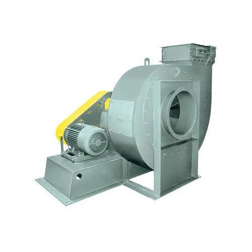
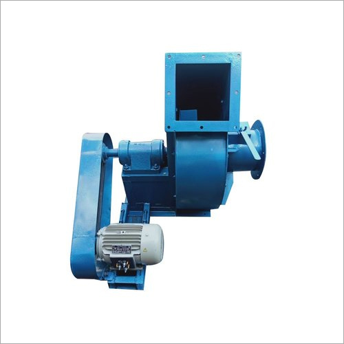 Belt Drive / Motor Coupled
Belt Drive / Motor Coupled Blowers
All Belt Driven Blowers are provided with EN-8 Steel shaft extension running in ball bearing of ample size with rigid housings. The whole blower with V belt drive is mounted on MS fabricated base plate.
- EN-8 Steel shaft with ball bearings
- Rigid housings for stable operation
- V-belt drive with flat pulley / couple
- Mounted on MS fabricated base plate
- Variable speed via pulley ratio change
Customise Your
Blower Configuration
Access Door
For quick access to casing interior and impeller for inspection and cleaning. The door is designed to match the scroll curvature and made leak proof with a gasket.
Split Housing
Easier access to impeller for maintenance and repair without full disassembly of the blower.
Drain Plug
A coupling or flanged type at the lowest point on the casing for draining of condensate or other liquid.
Dissipating Disc
Cast Aluminium disc for air cooling of the bearing and shaft, extending bearing life.
Gland Packing
For Chemical / Dust / Powder / Gas conveying blowers — prevents leakage at the shaft side on the casing.
What to Include
in Your Enquiry
To provide an accurate quotation, please include the following technical details when sending your enquiry:
- 01Volume in CFM or M³/Hr
- 02Static pressure in inches or mm of water gauge
- 03Direction of rotation and discharge
- 04Operating temperature
- 05Fan arrangement — Direct / Belt / Couple drive
- 06Any other accessories desired
Ready to Order?
Our engineers will respond within 24 working hours with a detailed quotation tailored to your requirements.
Send Enquiry+91-90168 77642